2026
MASONRY WALL PROPPING GUIDE
“The main cause of collapse during masonry alterations is overloading Acrow props due to the lack of awareness that the equipment capacity is variable.”
–
As every task is different, each project must be planned upon its own merit to ensure the most suitable equipment is chosen.
–
FITTING LINTELS WITHIN EXISTING MASONRY
Ensure to use the correct strength, length, size & variety of lintel for a task;
It is possible to purchase individual fabricated face brickwork lintels to specification for cavity and solid walls for the external and internal for the majority of lintel opening sizes which allows works to be completed safely as two separate tasks from inside and outside and allowing lintels to be purchased/fabricated in advance before the exact cavity size is known.
Within existing face brickwork ensure the lintel has a minimum bearing of 225mm at both ends; this extra bearing will help to support the lintel over the eventually toothed out brickwork below; when removing the rest of the opening in full and when bonding the new reveals into the existing face brickwork.
–
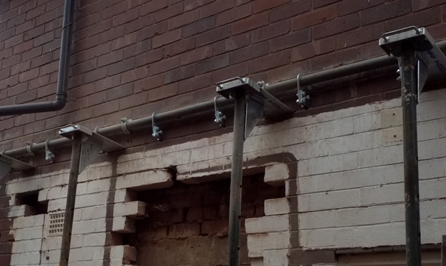
To prevent further instability and to reduce vibration to the remaining structure, remove the top mortar bed joint of the opening by either using a disc-cutter or preferably to minimise carcinogenic dust use a hammer drill fitted with a 6-8mm masonry drill bit before using a light set hammer drill with the correct chisel fitting to remove the bricks below. No club hammers as this only weakens the remaining structure. At this stage, only cut out the minimum depth of the opening to allow the fitting of the permanent support as seen within the photo below.
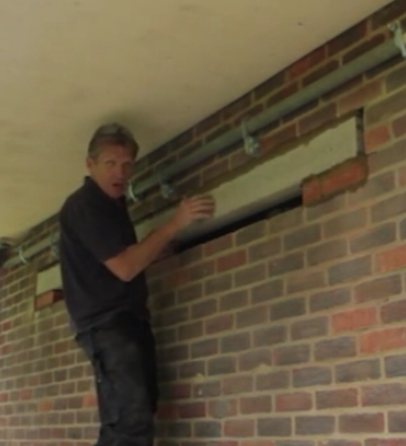
(Skill builder Roger Bisby demonstrating the effectiveness of the Brick Brace safety system. Giving clear access when fitting a specified 3150mm heavy duty 150mm deep concrete lintel to create a new window opening as the face brickwork was to be k-rendered at a later date, Internal steel was fitted internally as a separate task to reduce risk).
–
Once the lintel is bedded, cured & packed (including fitting cavity trays and feature work/soldier courses where required), carefully remove the rest of the opening in full.
When rebuilding reveals, fit/screw suitable wall ties vertically within both sides of the opening every 225mm and fit new insulation and cavity closures where required.
Internal Load Bearing Walls
Acrow props must always be used in the correct manner when working on load bearing walls due to the different live and static loads beams/joists maybe carrying.
Ensure rooms above are vacated and closed to clients to reduce live loads.
Always check the condition and shrinkage of timber joists and beams before propping, where in an unsatisfactory condition pack/replace/repair before continuing. Always work within Health and Safety guidelines and respect the welfare of your client’s, their family & everyone around you.
SASH WINDOWS
Older style sash window casings sit behind the brickwork face by an average of 100mm, therefore having a different internal and external lintel heights or lower face brickwork arches, which is another good reason to brace externally and to prop internally.
–
From existing finished floor level, the typical lintel height for window and door openings are between 2,100mm to 2,200mm. There are many variations of fitting lintels due to the different depth & variety of lintels, existing ceiling heights (typically 2.3m-3.2m) and the variation of the coursing and different variety/combination of materials used.
–
Fitting Lintels Under Load Bearing Floor Joists
The vast majority of heavy duty & boxed lintels require all of the internal masonry to be removed from below a 2.3m-2.4m ceiling joist height to allow for the correct lintel bedding & fitting.
–
Where shallower depth lintels aren’t fitted tightly to the underside of joists or upon higher existing ceilings heights; use tongued prop attachments below the separately Acrow propped joists to prop the masonry and to preserve existing coving/cornices when required.
–
To allow superior internal work access, prop the joists internally at a maximum of 400mm from the wall within the usual manner and remove the masonry from below joists so a lintel can be fitted with the correct bedding without impeding props within the direct working area, laying new masonry from the top of the newly fitted lintel to the underside of joists; pack with slate or similar when cured.
–
Fitting Lintels Under Non-Loadbearing Floor Joist Height
When joists are running parallel with the wall and not load bearing, tongued attachments can be used internally to support the load of the wall & using the Brick Brace externally for superior external fitting access.
–
FITTING STEEL BEAMS & P.F. C’s
The length of the opening and the weight of the load will determine the size, thickness, variety and depth of the steel and must always be calculated by a competent structural engineer to comply with building reg’s and for legal & public liability insurance reasons.
Do not attempt alterations in severe wet, gusty or windy conditions due to the further & unknown dynamic loads which could be created.
Within smaller openings upon 9”-13” solid/cavity walls two separate steels should be used where suitable and when steels can be fitted from either side of the opening which allows the project to be carried out safely as two separate tasks.
Within solid walls, create pockets through both sides and keep a sufficient amount of masonry within the second side to aid support before the first steel is fitted. Once the first steel is in position the remaining masonry can be removed to fit the second steel.
–
Choosing the most suitable equipment & method for a project depends on;
a, the length of the proposed opening and whether reveals remain to either one or both sides of the opening during the completion of the task.
b, the materials and weight of the wall & the other loads which require support.
c, The depth and direction of existing floor joists.
d, The overall thickness of the wall and/or the size of the cavity.
e, The internal finish & quality of the wall above, examples; plaster finished, dry-lined, lime mortar plastered or bare masonry.
f, The length, depth and finished height of the steel compared to the existing joist height.
g, The space required to remove any obsolete lintels and/or the fitting space required to fit the permanent support safely without dangerously overloading the equipment.
h, The size & material of bearings i.e. specified concrete pad-stones or engineering brick, (either solid or perforated) and/or design of the steel i.e. goal posts or boxed steel surround.
i, The existing structure, its history of previous works and the further variable site conditions.
–
When steels are specified it is usually for larger openings and/or for supporting higher loads when no load-point exists and where supporting all of the structure above including floor, roof, live, static & dynamic loads which is also a good indication that low & variable safe working load tongued prop attachments are not suitable to allow sufficient fitting access and/or to support the load safely or correctly.
The Temporary Works forum Description Of A Tongued Prop Attachment Within the 2017 temporary works tool kit, part 10
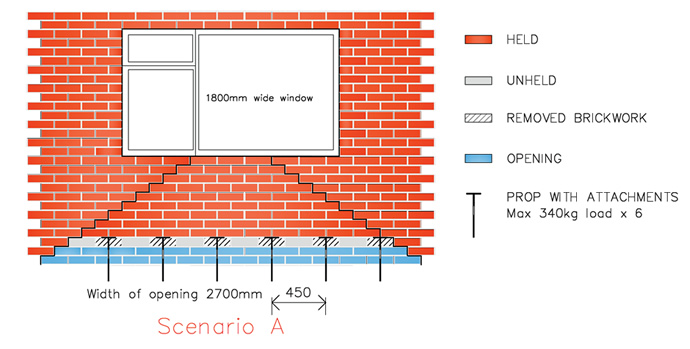
Steel plates (approx. 150mm × 350mm) that fit onto the head of an adjustable steel prop (‘Acrow’). The plates can be cut into the mortar joint above the new lintel. They will be positioned at relatively close centres (around 750mm) and rely on the brickwork arching between them. They can typically support loads of around 350kg (as the applied load is eccentric to the prop) and are generally used for openings up to around 3m wide, with heights less than around 3m. If an opening is to be formed in a thick wall, or the opening is wide, then a designed needling scheme would be required. The needles should be positioned not more than 1m apart and the load on each needle should be calculated.
–
Do not leave an eccentrically loaded prop or braced masonry opening overnight without also propping concentrically as both methods are designed for access during a task and not a substitute for a correctly used Acrow prop when unattended. Due to live, static and the unknown and variable dynamic loads, leave sufficient masonry in place or wedge, prop, dry pack or build at sufficient points within the new opening at the end of the working day when a permanent support is not in place.
—
Pad-stones & Engineering Bricks
Either fit the specified pad-stones after a steel is in the final position by propping the steel once under the wall, or preferably and to allow mortar curing time; fit the pad-stones days before inserting steels, the use of rapid set cement can also be favourable in the small quantities that is required in this situation.
–
Remove the bearing masonry to accommodate the pad-stones. Once steels have been correctly fitted and packed and the mortar cured, remove the rest of the opening to the full depth.
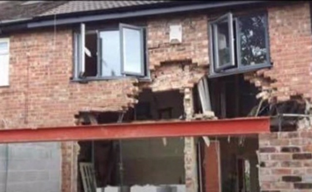
It is proven through risk assessments that the safest procedure is to remove only a sufficient amount of masonry to allow the fitting of the permanent support. Unless site and structure conditions permit, an opening should not be removed down to the full depth to gain the correct fitting access for mechanical lifting equipment as it increases the risk of greater collapse due the masonry having a larger void to fall and also creates a higher risk of accidental knocks & removal of fully loaded props during demolition and should be avoided at all costs as seen in the recent viral Facebook video of collapse in January 2020.
—
Telescopic lifting equipment when used externally is only suitable when the scaffold arrangement allows this.
The top of Scaffold board height is recommended to be flush & between1100mm-1400mm from inside finished floor level upon a typical 2.4m existing ceiling height which allows fitting at a comfortable workforce waist height.
—
Load Bearing Walls;
Fitting a steel under load bearing joists and creating a 200mm-300mm bulk head between the joist height & new opening;
This installation is the easiest and cheapest solution to a rear extension knock through; averaging £400 per linear metre nationwide.
Prop the underside of internal joists down to a sufficient base and position at a distance of 400mm from the wall to allow sufficient working space/access for masonry and old/existing lintel removal.
Where suitable, the Brick Brace safety system is fitted externally and used to brace the exterior skin which in return, supports all of the brickwork and reduces the weight of the load and also allows a safer working space as fewer impeding props if any are required, depending on the opening size.
—
Fitting Steel Beam At The Same Height As Existing Load Bearing Floor Joists To Remove A Bulk Head From Over An Opening
This installation is far from simple and more difficult and time consuming; averaging £700 per linear metre plus further “making good”/remedial work costs.
Steel/s are installed at the same level as the 1st floor joists and fitting the joists into the web of the steel which is prepared & measured beforehand with bolted timbers inserted into the web and correctly positioned joist hangers attached which prevents a rather nasty difficult and tight working space when fitted later and allows the hangers wings to be fitted over the built in steel.
The floor joists would be propped from underneath and accurately cut from below to fit within the hangers, the Brick Brace fitted externally as the steels can only be fitted from the external side. This method is only appropriate when the steel beam depth is similar or smaller than the existing joist depth;
where the existing joists are shallower than the new steel the props and needles method should be used as the steel would sit higher than 1st floor level and repairs within the rooms above would be required at skirting level.
Further Option
The option below will increase structural engineer and fabrication costs however it will minimise risk of collapse during the task and safely reduces internal 1st floor wall damage & minimises labour and time costs.
Resolves the problem at design & fabrication stage by welding a bottom plate with further welded gussets at 600mm centres onto the PFC of which supports the existing floor joists. This option is only available when the opening size is suitable and when designed by a competent structural engineer
—
Non-Load-Bearing Joists
(Joists that run parallel with the wall and beam hidden within the ceiling void)
This installation is difficult and time consuming; averaging £800+ per linear metre nationwide and can treble in price when designed as a boxed frame surround.
Existing internal floor joists are propped from below and the Brick Brace fitted externally when suitable as the steels can only be fitted from the external side. This method is also only suitable when the steel beam depth is the same or smaller than the existing joist depth; where the proposed steel is deeper than existing joists the props and needles method must be used as the steel would sit higher than 1st floor level and repairs within the rooms above are required at skirting level. Propping with needles externally and using a sole plate under the needles over existing floor joists internally with the joists propped from underneath at ground level, using the Brick Brace externally which stabilises the lateral strength which all existing propping methods rely upon to work safely.
 Where steel depth is larger than joist depth; Needles are fitted through both skins of the wall with the external propped down to solid compact ground and not from a block & beam floor. The internal side of the needle is packed off the existing first floor using a spreader plate, then by propping from the underside of ground floor ceiling down to a substantial base that can safely support the load internally.
–
A more knowledgeable architect would discuss the options to the client prior to design and give the most suitable method to tackle the task within the drawings specifications and is not the client’s decision to choose which method is used as safety is so often compromised in this situation.
When the builder is at costing stage and a client insists that no needles holes are to be inserted into the rooms above, ensure the client fully understands the situation, also add within the contract that you the builder waiver responsibility and that the client/owner takes full responsibility of using less suitable equipment.
–
Further Options
A
THE SACRIFICIAL BRICK BRACE BRACKET
Fitted externally and designed to support the internal skin when fitting lintels or steels at the same level as existing joist height that run parallel with the wall, within 9″ solid or cavity walls, preventing the upheaval and unnecessary repairs to within finished bed/bathrooms above.
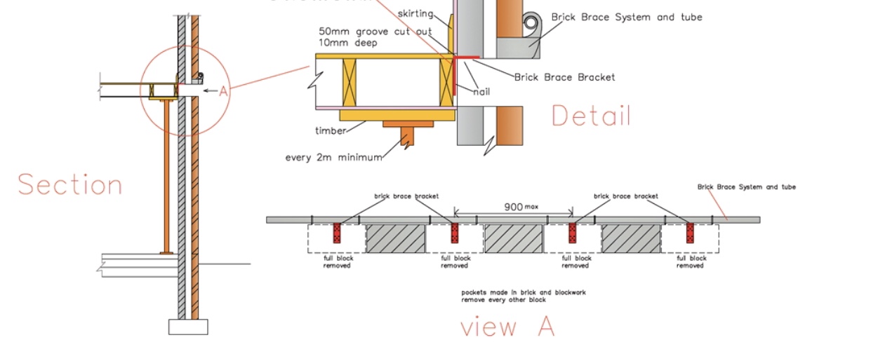
When suitable; fit the Brick Brace safety system over the full length of the proposed opening on the external brickwork wall.
Fit props and needles within the rooms adjoining the finished room/s.
Create pockets through both skins of the wall every 450mm, (2 brick lengths) with the hit and miss method as seen in view A within the drawing above. Before fixing the brackets, inspect the condition & suitability of the joists, and check for cables, pipes and all other fittings.
Once thorough inspection is cleared, screw the sacrificial brackets into their permanent position at a maximum of 900mm centre’s ensuring a close and snug fit. The remaining masonry can then be removed to fit the steel.
The Sacrificial Brick Brace Bracket is only to be used when the walls above are in good order with no signs of movement or cracking. The 1st floor joists require propping from underneath within the usual manner at 1,200mm centre’s as seen within the drawing above.
Please Note;
The brackets are only available by contacting us directly and providing us with the information we require to ensure project suitability.
Further Option B
Use a diamond core drill to create clean easy to fill holes and use smaller needles to reduce internal 1st floor wall damage where possible and with a far superior safe working load of any overextended tongued prop attachment.
Please note;
This guide is to raise safety awareness and for the purposes of showing that every project is different with guidance on further options where existing equipment would be dangerously misused to complete a task.
As with every small project within the construction industry it is the legal duty of the competent individual in charge of the work force to plan and prepare a correct procedure & sequence of works most suitable for the site conditions and to carry out the project with enough precaution to reduce risk of human error and accidents. The refurbishment & small domestic projects sectors have approximately 40% of the yearly accidents, injuries & fatalities from the whole of the British construction industry.
–
Due to an incredible amount of task variations, we recommend the guidance of a competent & knowledgeable structural engineer that specialises in temporary works when in any doubt; as rectifying even the smallest of mistakes can be dangerous, time consuming & very costly.
—-
The main cause of collapse is overloading due to underestimating the weight of the load and removing tongued prop attachments from the wall to avoid 1st floor wall damage and/or attempting to gain more fitting/working access, as over extending an eccentrically loaded Acrow prop greatly affects the safe working load.
–
(An Acrow prop is 50mm away from the wall when maintaining the max 340Kg S.W.L )
When fitted with a Strongboy or any other similar designed product an Acrow props safe working load decreases by at least 90%, from 3,400kg down to the maximum 340kg and can even reduce down to 0kg of which depends on the size & the working height of the Acrow prop, how plumb, how tightly fitted and how far the Acrow prop is positioned from the centre of the wall.
–
A Strongboy was designed in the mid 1980’s when the typical opening was smaller and a cavity size was only 50mm but due to changes in construction design a cavity has now doubled to 100mm and over 150mm upon new properties for further thermal value and with open plan living accommodation vastly increasing opening sizes within a typical residential rear extension.
Attempting tasks which require longer & wider steels with welded top/bottom plates for large openings and bigger cavities and still only using Strongboy’s is where more problems of overloading through over extending even further from the wall to gain sufficient access arise.
–
Load-Point
Which masonry requires support?
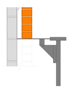
A 45 degree angle upon half bonded block work, a 35 degree angle in a Stretcher bond and a 25 degree angle upon a Flemish or English bond, from both ends of the opening, up through the bed and perp joints carrying on up to the central perpendicular joint where both angles meet is the location of a load-point.
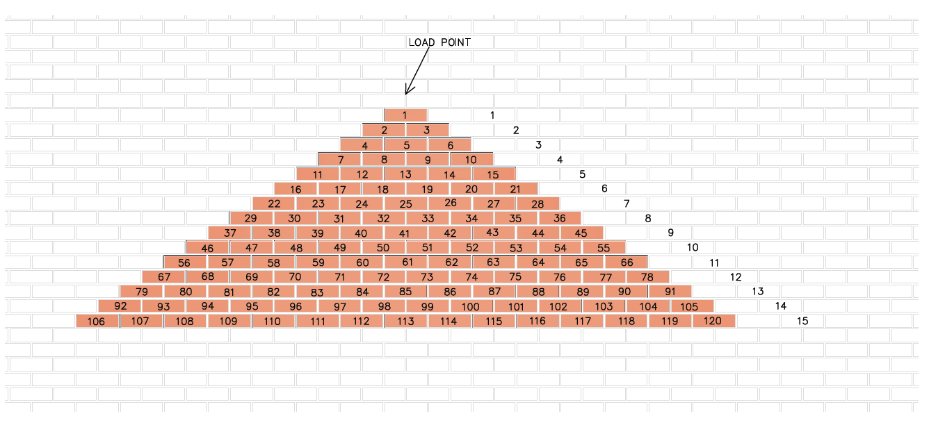
When an opening is made within an existing wall and a load point is intact, the triangle of brickwork above the opening is the only masonry that could collapse, therefore this is the only masonry that requires temporary support.
–
This small triangle of masonry is what Strongboy’s were designed to support when fitted 900mm apart and used within 215mm eccentricity at a maximum height of three metres when used upon a size three Acrow prop.
–
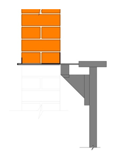
Upon larger openings within a typical two storey residential property and any of the 3 points of the triangle do not remain, this law changes and all of the weight of the storey height above will rest back over the length of the opening (including roof loads, when they apply) due to the masonry above not safely arching.
This masonry & further loads can weigh up to 10 times more in most cases than just the smaller triangle and is why Strongboy’s are so easily overloaded upon wider openings.
–
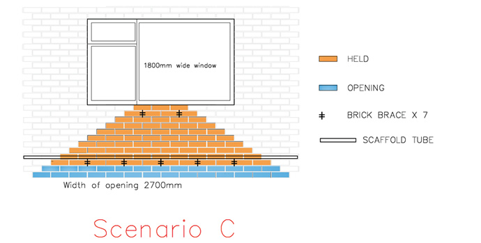
Fit the Brick Brace to reinstate a load-point, as shown within the drawing below to safely reduce the weight of the load back to the small triangle of masonry and to minimise the amount of impeding Strongboy’s required without dangerously overloading the equipment.
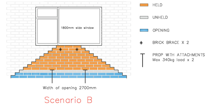
(Scenario C below, shows the Brick Brace Safety System being used within a lime mortar mix)
The Brick Brace Safety tool, weight charts, correct procedures & proven strategies address all the main causes of minor and major collapse during masonry alterations.
(Please view our masonry weight awareness chart for further guidance).
–
Due to thirty years of misleading instructions and inadequate warnings the Strongboy has falsely eased a difficult task and increased the risk of the user to overload a structure and also suppressed the true level of knowledge required to carry out masonry alterations correctly.
–
PLANNING A TASK
CHECK LIST
What is the nature of the task, is it remedial works, fitting cavity trays or fitting/repairing a permanent support? Is it forming a new opening or increasing the size of an existing opening? Is the opening in a 4″single skin of masonry, two skins or even more? Is the opening in an internal partition wall? Or is an opening in the outer or the inner leaf of a cavity wall or in both sides?
–
What is the age and condition of the masonry and what is the masonry material? What design (cavity or solid)? What is the size of the cavity? What thickness is the wall? Which bond is the masonry and which mortar mix, cement or lime?
–
What are the existing ceiling heights? What are the size and direction of floor/joists, are they load bearing onto the wall or are they non load bearing? Does the existing floor impede the internal fitting access? What is the condition of the internal wall? Is the internal wall plastered or dry-lined or bare masonry as in the case of the majority of total refurbishments? Are there any signs of movement, e.g. cracking?
–
What height is the opening, ground floor, first floor or higher? Is a permanent support fitted underneath joists? Are the existing joists fitted within the web of the permanent support or is the permanent support fitted at the same height or below non load bearing joists?
–
What opening size (including bearings) is required? Is a load-point intact? What is the total weight of the load that requires support? Which variety of lintel/s steel/s are specified or most suitable? What are the length, depth, width, thickness and weight of the permanent support/s? Is the permanent support/s deeper than existing floor joist depth?
–
How will the new permanent support be fed into position and how will any old lintels be removed? Which equipment or variety of temporary support equipment is designed to stabilise the structure, supports all of the masonry correctly and also provides sufficient fitting work access without dangerously over extending and overloading the structure above?
–
The More Methods Known, The Safer & Easier The Different Tasks Become!
Temporary support equipment options in alphabetical order; Acrow props, Brick Brace, Needles, Prop-Wise and Strongboy’s.
–
Using the Brick Brace in-conjunction with the traditional propping methods reduces labour & repair time without cutting corners or compromising safety, supports the masonry in between props and also improves the unknown variable lateral strength of bonded face brickwork which all existing propping methods rely on to work safely;
Brick Brace with Acrow props, Brick Brace with Needles, Brick Brace with Prop-Wise or Brick Brace with Strongboy’s and depends on the task at hand of which variety is most suitable.
The Brick Brace counter acts all of the hidden problems of only propping masonry.
–
The Maximum Safe Working Loads
(S.W.L)
–
A plumb & concentrically loaded Acrow prop concentrically loaded upon the axis (load bearing from head plate down to foot plate), 3,400Kg.
 –
–
An Acrow prop used within the props and needles method and allowing a maximum 25mm eccentricity from the centre line of the Acrow to the centre of the needle, 1,700Kg.
–
Without warning a Strongboy dangerously misuses the Acrow prop due to the severe eccentricity of the load and because the web of the Strongboy changes the direction of the load onto the side of the Acrow props inner tube of which is designed only for vertical loads from the head plate down to the foot plate.
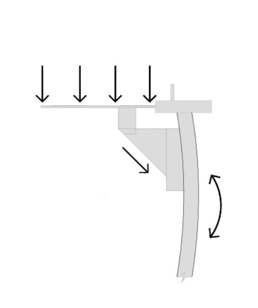
An eccentrically loaded Acrow prop curves and loses height when overloaded or over tightened which is the legal duty of the user not to overload and to work with an Acrow prop fitted with a Strongboy in a safe & professional manner even though no warning of this is in place.
–
The closest thing to madness is attempting tasks which require longer and wider steels with welded top/bottom plates for wider cavities and still only using the out of date Strongboy as the safe working load is severely compromised by over extending even further from the wall to gain more fitting space.
–
We do not endorse the misuse of any temporary masonry support equipment however as it’s done on a daily basis throughout Britain and upon tutorial You-Tube videos by so-called professionals, we highly recommend bracing the masonry beforehand as a safety belt to reduce the high risk of collapse and to prevent the same needless re-occurring accidents on site.
Any structural engineer, temporary works co-ordinator or builder that assumes eccentrically propping upon 102mm of the end of a bendable Strongboy tongue can safely support 340Kg of masonry upon the face side of a cavity wall without also bracing the masonry is not knowledgeable enough to design temporary support works.
–
To please a client an architect has the artistic freedom to design & draw any new opening size they wish within existing masonry with a few lines and a rubber and with no care of how it is done in real life.
–
A structural engineer can provide the method of using the out of date Strongboy, which may save time by cutting corners but also compromises the builder, work colleagues & clients safety as the method doesn’t allow the correct fitting work access without dangerously overloading the structure above.
–
Upon this assumed, generic and out of date calculation, the builder purchase/hire Strongboy’s of which are supplied with zero guidance and are sold by a vast majority of retailers with limited masonry alterations knowledge, and when the obvious accidents of overloading continue to re-occur, only the builder is at fault and fined or worse case scenario imprisoned for corporate manslaughter where collapse causes a fatality.
–
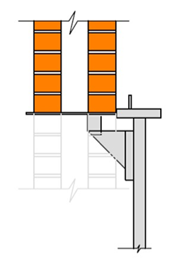
To maintain the maximum 340kg safe working load, the tongue of a Strongboy must fully penetrate the internal skin when supporting a cavity wall, as seen in the drawing below.
When the Acrow prop is removed from the wall to avoid internal wall damage or to gain more fitting work space, the safe working load reduces to an unknown quantity.
–
As also seen in the above drawing; for the web of the Strongboy not to impede the fitting space the tongue is to be fitted at least 215mm (three brick courses) above a proposed finished lintel height and any masonry below the tongue is not supported safely.
–
The tongue of a Strongboy is designed to support two skins and is too long to support only the outer skin of a cavity wall when the internal skin of masonry impedes correct use, the safe working load is severely reduced to an unknown quantity and should be avoided as there are now safer options available.
The misleading theory behind the Strongboy is to use fewer Acrow props and to reduce masonry damage and is marketed within that manner, which certainly is not the case when the maximum safe working load is only a fraction (1/5) of the correct propping and needling method and when maintaining the 340kg safe working load the hole within both sides of a cavity wall or a 9″ wall is actually larger than fitting a needle and with at least five times more fitting holes required than one 1,700kg safe working load needle.
–
A full 360 degree turn of the adjustable collar raises the working height of an Acrow prop by 8mm, jacking or over tightening can dangerously overload an Acrow prop especially when eccentrically propping with a Strongboy as the distance from the masonry to the solid base will not change, only the Acrow prop or the Strongboy will deflect or distort.
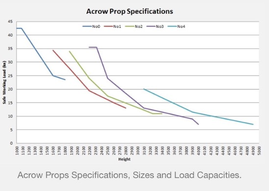
As seen in the graph below, the safe working load of an Acrow prop reduces when the inner tube of an Acrow prop is raised from the outer tube, ensure to use the correct sized Acrow prop most suitable for the height of the task.
To reduce the risk of curving the inner tube of an Acrow prop, it should not exit the outer tube more than 50% when eccentrically propping.
An overloaded Strongboy is solely relying on the lateral strength of the masonry to avoid major collapse which is why the Brick Brace should also be used to strengthen the masonry when propping, especially within lime mortar masonry due to its weaker strength.
–
When working upon load bearing walls, plumb and concentrically loaded Acrow props should always be used to support roof timbers, joists and beams separately due to the different live/static loads they may be carrying. Check the condition of joists and beams before propping, where in an unsatisfactory condition replace or repair before continuing.
–
Do not attempt external masonry alterations in severe wet, gusty or windy conditions due to the unknown and further dynamic loads.
–
To reduce live loads when fitting a permanent support within active living accommodation ensure the rooms above are vacated and locked/closed.
–
Respect your legal responsibilities and respect the welfare of everyone around you.
—
THE STRONGBOY INSTRUCTIONS WERE CHANGED IN NOV’ 2015
And now start with;
Prior to using any Strongboy masonry support, you should identify that this is a suitable method to carry out the intended works.
TWO SECTIONS OF THE OLD INSTRUCTIONS
1
(Correct)
On normal cavity walls the maximum distance from the centre line of the Acrow prop to centre line of the cavity wall is 215mm ( 9″ inches) or using the leading edge of the hammer plate as a guide, measure 150mm to the centre of the cavity. See drawing below.
2
(Misleading)
For a wider hole on stable walls the Strongboy’s should be positioned a maximum of 900mm apart.
–
TWO SECTIONS OF THE COINCIDING NEW STRONGBOY INSTRUCTIONS
(updated November 2015)
1
(Correct)
The distance between props should be calculated from the assessment of the loading. Always use the correct number of Strongboy’s for the job.
A Strongboy can be used on single or double skin walls where each leaf is up to 4 ½” (112mm) thick. If double skin, the maximum cavity is 2” (50mm).
2
(Misleading)
Ensure the blade of the Strongboy is fully supporting the second skin.
–
The misleading instructions of the Strongboy increase the risk of the user to overload the equipment and to underestimate the weight of the load that requires support and has also suppressed the true level of knowledge that is required to safely tackle the many different tasks of masonry alterations.
–
Examples
A
9″ brickwork can weigh over 600kg per square metre, (120 bricks plus mortar) which would require at least five Strongboy’s per linear metre (at 167mm centre’s) on a larger opening on a typical two storey residential property which could weigh 1,440kg per linear metre without roof loads and making the use of Strongboy’s unsuitable for the particular task.
B
A Strongboy was designed in the mid 1980’s when the typical cavity size was only 50mm but due to changes in construction design a cavity has now doubled to 100mm and even up to 150mm upon new properties, with open plan living accommodation increasing the opening sizes within a typical residential extension.
Attempting tasks which require longer & wider steels with welded top/bottom plates for large cavities and still only using Strongboy’s is where more problems of overloading through over extending from the wall arise.
C
The new instructions (updated Nov’ 2015) strangely suggest that propping an older style 9″ wall by over 390mm eccentricity from the centre line of the wall to the centre line of the Acrow prop is acceptable even when the safe working load is reduced to an unknown quantity and when to avoid collapse the Strongboy is totally dependent on the unpredictable & unknown lateral strength of the weaker lime mortar masonry.
D
Within the new instructions there is no mention of the maximum eccentricity of 215mm. All measurements are taken from the end of the bendable and over sized tongue, “If” this was a correct method of measuring eccentric loads it is actually safer to support a 100mm cavity wall which is not permitted than supporting a 50mm cavity wall which is permitted, as the measurement from the centre line of the Acrow prop to the centre line of the wall is 25mm less eccentric.
E
The majority of tasks require far more fitting work space than the Strongboy can give when still maintaining the maximum 340kg safe working load and when not dangerously removing the opening down to the full finished level without the permanent support being fitted as this increases the risk of collapse through accidental removal of loaded Acrow props during the demolition of the masonry. To reduce the risk of minor and major collapse only a few courses of masonry should be carefully removed to allow for the safe fitting of the permanent support. Once the permanent support is in the final position and cured, then the rest of the opening can be removed down to the required depth.
–
To change rules and instructions of a product can not be lawful when they dangerously reduce the S.W.L to an unknown quantity and endorses further misuse of which creates a higher risk of collapse.
–
Due to the patent expiring there are now approximately 15 companies and sole traders that sell similar designed products as the “Strongboy” with the majority being sold without the correct level of testing or written instructions of which both are required to comply with the provision and use of working equipment regulations and yet the H.S.E do nothing about it due to their inability to address the issues without accepting the responsibility of the fault of which they have helped to create due to allowing misleading instructions for over thirty years and accepting test results which do not reflect site conditions, as clearly seen in the advertised test drawing below.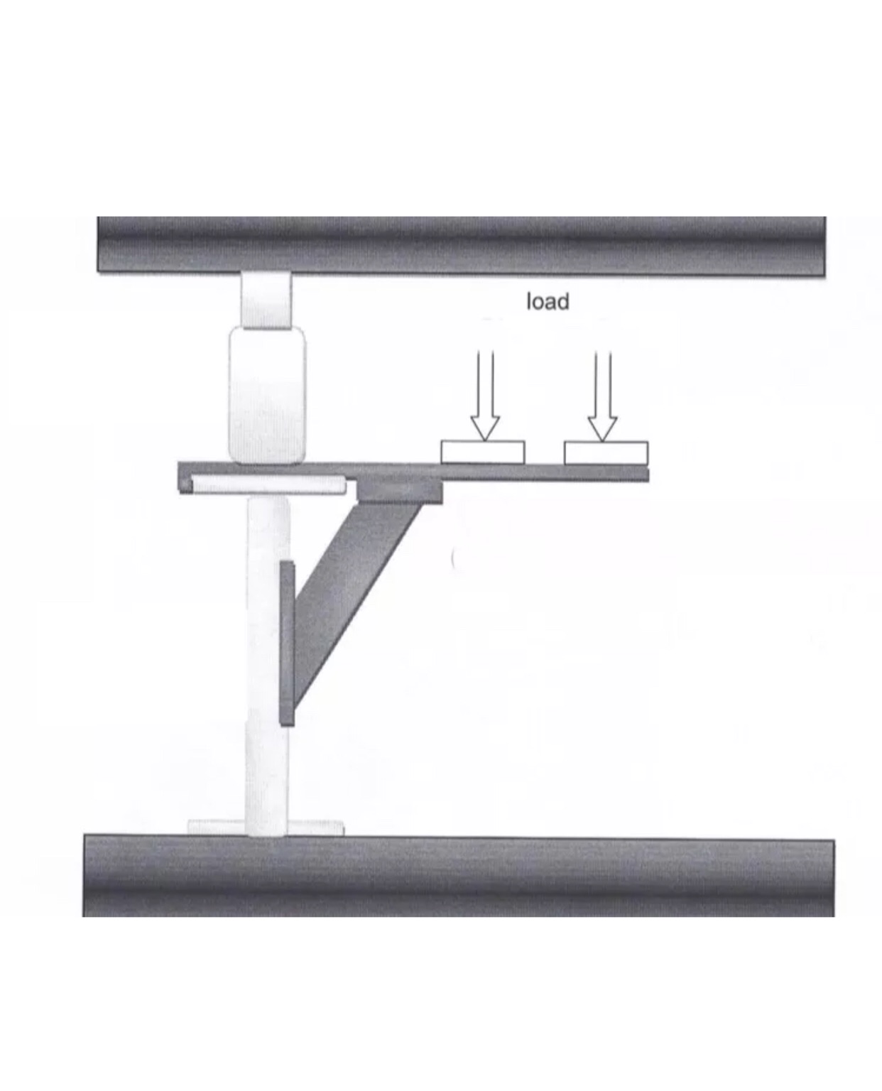
The list of new companies and sole traders that manufacture copies will continue to grow and the quality will be sacrificed to become the least expensive if no correct instructions of use or proper tests upon an Acrow prop are required and when the H.S.E do not police the problem in a safe & correct manner.
Through our own professional research, we have uncovered that no temporary masonry support equipment is safe to use unless it is provided with written guidance and a correct procedure as this reduces assumptions of correct use and because we do not want anyone to misuse our products we provide full instructions and guidance with every product we sell.
—-
C.R.O.S.S.
2008 Newsletter
Confidential Reporting On Structural Safety.
When carrying out temporary needling and propping one of the most important aspects is to ensure that the props are concentrically loaded and plumb.
–
The use of a steel bracket on top of the prop giving a minimum eccentricity of 200 mm would not seem to be such a good idea?
–
Interestingly such a product does exist and has proved very popular with builders who see it an advantage to prop only one side of a wall.
–
The prop is sold and hired from builders’ merchants with minimal safety instructions and is potentially unsafe due to bending moments being introduced by this product into Acrow props designed only for axial compression. Any device that modifies the behaviour of props by introducing bending moments is potentially hazardous.
–
Another reporter has come across these in use and in his view they must only be used in the case of limited openings where the masonry can arch over leaving only a small triangle of masonry below the arching that can potentially break away.
–
All in all these are for light use only and never for heavy shoring. The reporter thinks that the manufacturers, and possibly the hire companies, would be negligent if they did not provide some guidance on the use of such prop head plates.
–
Another reporter has frequently seen builders using props with cantilevering head-plates which cause the supporting props to bend. Some years ago he photographed a set of such props which had very noticeable curvatures. The wall above had dropped in consequence causing damage to the building and resulting in a substantial claim against the builder. The reporter generally advises builders not to use such head-plates.
–
Correct propping is essential and temporary works failures are a recurrent theme on site. It appears that this type of prop should only be used in specific low risk circumstances.
Structural Engineers Cambridge Ltd
(Taken from their website)
Temporary Support
This is one of the most tricky parts of our job, as one of the most hazardous times in the construction or alteration of a building is when the works are in progress.
As consulting engineers, our brief is normally to design the permanent parts of the structure, and in the traditional contract model the contractor is responsible for the design and execution of the Temporary Works. Thus, the conscientious contractor would employ his own consultant to provide him with the necessary design.
The Building Inspectors are also only responsible for ensuring that the permanent works are carried out in accordance with the specification, so unless the temporary works are an immediate risk to life and limb they are not empowered to enforce a particular method.
Supporting Walls
Regrettably, in domestic projects the builders are too often inexperienced or unaware of the correct practice for supporting walls and other parts of a building. I am often appalled when I visit a site to see the back wall of a house knocked out to receive a lintel, with no props supporting the masonry but plenty of Acrow props beneath the first floor. As the wall comprises the majority of the load, this is clearly not right!
The argument is often put that the wall will somehow “arch” over the opening, and in some cases, with smaller openings, it does. However, as current projects demand ever larger opening widths, the ability to arch is eliminated by the lack of restraining walls either side, and the effect of window openings in the storey above.
So, if the props are only placed beneath the first floor, the wall can only be supported by resting on the ends of the floor joists. In practice, most joists have a gap above them due to shrinkage as the timber dries out, so the floor will either be jacked up or the load is transferred into the skirting board. In older houses, these are attached to the wall with cut brad nails every 18″ or so; in newer houses they may be screwed or stuck on with “No Nails”. As a storey height of 9″ thick brickwork weighs over a tonne per metre run, there is no way this could be considered safe!
Needle Beams and Props
The “textbook” method for supporting a wall is to punch holes in the wall every 90 to 120cm and insert needle beams through the wall. The ends of the needles are propped, leaving a working space beneath for inserting the lintel. This is reliable and robust, however the common objection to this method is the disruption to the rooms above (one of which is inevitably a fitted bathroom!) and the need to repair the holes afterwards. This has to be the preferred method for the majority of projects, however.
Strongboy Heads
A common method in small projects is to use “Strongboy” heads. These are fabricated steel fittings that fit over the top plate of an Acrow prop to give a projecting spade-like blade. This is inserted into a slot cut into the bed joint of a masonry wall, so that the wall can be supported while the prop does not have to be directly below the wall.
The convenience of this method is undeniable, but due to the limited load capacity of these devices their safety is too often overestimated or taken for granted. The manufacturer’s stated load capacity is 340kg, which amounts to about one square metre of brick and block cavity wall. This means that you would need supports every 450mm to avoid overloading the Strongboy heads. For solid 9″ brickwork, the supports would need to be virtually touching each other!
In practice, the supports are normally spaced at one metre intervals, and the props are overloaded, causing cracking to the supported wall and bending the blades of the Strongboy heads. I have experienced several cases where unwitting builders have caused extensive damage using this method, and I believe that insufficient information on their proper use is provided when they are purchased or hired.
—–
ACROW PROP GUIDANCE
–
As seen in the graph below, a size no1 to a size no3 Acrow prop have maximum safe working loads of approximately 3,400kg with a size no3 reducing down to approximately 600kg when the adjustable working height is fully raised at four metres.
Between the height’s of 2.2 metres to 3 metres, a size 3 Acrow prop (purple) has a far superior safe working load than a size 1 or size 2 Acrow prop (red and green), ensure to use the correct sized Acrow prop for the task at hand.
–
A Strongboy has a maximum safe working height of three metres from a permanent solid base.
–
Acrow Props exhibiting any of the following defects should not be used;
A tube with a bend, a tube with more than superficial corrosion, a prop with a bent head or base plate, an incorrect or a damaged pin or a pin not properly attached to the prop by the correct chain or wire.
–
Install props vertical to ensure that it can support its specified load. Props must never be used more than 50mm out of true vertical for every 1.8m in height as this severely decreases the S.W.L.
–
Ensure the base of the prop is bearing directly onto the surface and that the surface is capable of supporting the weight that will be placed upon it. Screw props to surfaces and spreader plates where possible to reduce the risk of collapse through accidental skids, knocks & movement.
–
Forked prop attachment heads should be used to reduce eccentric loads and to ensure a superior safe working load when using needles.
–
Lime mortar masonry acts differently than cement mortar masonry during alterations which is why the Brick Brace should also be used when possible where propping lime mortar masonry.
The New Strongboy Instructions But still Not One Mention Of A Load-Point
–
Taken from the Strongboy Ltd website
(updated Nov’ 2015)
Prior to using any Strongboy masonry support, you should identify that this is a suitable method to carry out the intended works.
You must correctly identify all loading that the Strongboys will have to support. The total load may simply be the masonry above the opening, but it will also include loads from a floor and/or a roof that is supported by the wall. Floor loading may need to include any heavy furniture in an upstairs room, a full bath, people walking on the supported floor, etc. Roof loading includes supported timbers/steelwork, roof tiles, loft mounted water tanks and the like.
It is recommended that only one single opening in any one length of wall be created at any given time.
You should check that the wall masonry and any floor/roof timbers are in good condition prior to any work being carried out as remedial work may be needed prior to the opening being altered or created.
Strongboy Masonry support is not recommended to be used to provide temporary support to unstable structures.
You should obtain competent structural engineering advice if there is any doubt about the condition of the structure or the nature of the loading, or if any unusual loads are suspected.
!!!CAUTION!!! STRONGBOYS ARE HEAVY AND MAY HAVE SOME SHARP EDGES. ALWAYS WEAR PROTECTIVE GLOVES AND APPROPRIATE PROTECTIVE CLOTHING / FOOTWEAR WHEN HANDLING !
Instructions for use:
Mark the wall in the correct position where the Strongboy is to be inserted
Scrape or grind out the mortar, or remove a brick prior to insertion of the Strongboy in the identified position. Always ensure the underside of the brick to be supported is clean and will sit flat on the blade of the Strongboy.
The Strongboy is designed for use with standard telescopic screw props with a 6” x 6” (150 x 150mm) head. Strongboys should not be used on struts as these have a much smaller head. The prop should only be placed on firm, flat, compacted ground that is capable of supporting the load. A sole board should be placed under each prop – eg 18” x 9” x 1½” (450 x 225 x 36mm)
Hold prop vertically upright with one hand close to where the intended usage is.
With your other hand holding the supporting web, tilt leading edge of Strongboy blade up approximately 30 degrees.
Lower the leading edge of the Strongboy blade until the web bracket is located against the vertical tube of the plate and the blade of the Strongboy is horizontal.
To check the Strongboy is correctly engaged, pull the front edge of the blade down. The Strongboy should not move.
The Strongboy may now be manoeuvred into the correct position for use.
Insert the blade into the mortar space or brick hole until the blade is at least at the same depth as the rear of the brick on the leaf of the wall which is intended to be supported. Where possible the Strongboy should be inserted until the tip of the web is nearly touching the wall.
Ensuring the prop remains completely vertical and in plumb, tighten the collar of the prop until the Strongboy and prop are fully engaged with the wall and do not move. Do not over tighten as that may cause the blade to bend. Hand tight is generally sufficient. Over tightening may damage the brickwork and the prop and Strongboy and may cause the blade to slide out of the brickwork.
Maximum load bearing capacity of 340 Kgs per unit (750lb )
Maximum safe working height 3 metres from firm base .
The distance between props should be calculated from the assessment of the loading, but in any case, it should not exceed 3ft or 900mm.
Always have the loadings checked and use the correct number of Strongboys for the job. If in doubt, you should obtain competent structural engineering advice.
If the width of the intended opening is greater than 4m we recommend that the props be horizontally laced and diagonal braced together using scaffolding poles and proprietary couplings .
The Strongboy can be use on single or double skin walls where each leaf is up to 4 ½” (112mm) thick. If double skin, the maximum cavity is 2” (50mm). Ensure the blade of the Strongboy is fully supporting the second skin.
Check that the prop is not working loose on a regular basis – eg continuously while the opening is being made, otherwise daily. Arrange the work so that the Strongboys and props are not knocked or displaced. If this could happen then lacing and bracing using scaffold poles and fittings can help prevent accidental movement (standard fittings onto the prop inner tube and 68.3mm fittings onto the outer tube).
Superior Instructions Of A Similar Designed Product
–
DO NOT use this equipment unless you have read and understood these procedures.
A COMPETENT PERSON MUST CARRY OUT A SPECIFIC RISK ASSESSMENT AND PROVIDE A SAFE SYSTEM OF WORK (TEMPORARY SUPPORT PLAN) BEFORE USING THE SPARTAN SUPPORT PROP.
RECOMMENDED USE OF SPARTANS
Propping of brickwork/lintels when removing a lintel and filling in door and window openings
Fitting of one new RSJ beam, concrete lintel or timber header beam at a time over a new or existing opening.
SAFE WORKING LOAD OF SPARTANS
A Structural engineer experienced in temporary works should always be appointed to assess the building and establish a temporary support plan for the work to be carried out. The assessment must include working out the load to be supported. This will include the weight of the wall above the opening and the effect of any timber or steelwork that is in turn supported by the wall that is to be worked on. The load to be supported must be checked against the safe working load of the support equipment to determine how many supports are required and the position of each support.
The temporary propping design should include a start to finish sequence for carrying out the work and set out suitable methods for conducting the work. In some cases, involving creation of a new opening or major changes to the existing arrangement it may be advisable to brick up any redundant openings first. It may be necessary to fit and cure the new lintel prior to removing the full panel of masonry below it.
Think about the weight of the new lintel and how it will be fed into position (and how any old lintel will be removed). Make sure that the Spartan and prop locations will allow the lintel to be fitted easily.
If the temporary support design would require Spartans to be placed side by side, then cantilever prop attachments are unlikely to be suitable for the job and an alternative propping method should be used – such as propping both sides of the wall with the wall load carried on a series of needles that pass through the wall.
All design and temporary works procedures should be carried out in accordance with the latest version of BS 5975
RECOMMENDED SAFETY FOR THE USE OF SPARTANS
Only use Spartans to create one opening at a time.
Always ensure there is sufficient masonry at either side of the opening to carry permanent and temporary loadings.
Do not use Spartans in deteriorated or unstable masonry.
Do not exceed 900mm spacing between props.
Do not exceed the certificated testing SWL of 360kg for both the large and regular Spartans.
Spartans load tested up to a maximum height of 2900mm using a number 1 Acrow Prop. Note that this figure is the distance from firm, level ground to the Spartan blade. Each prop should rest on no more than a single sole board that is in full contact with the ground.
When fitting use a spirit level to ensure each support, prop is vertical in both planes
Check frequently to ensure the Spartans/support props are secure, supporting the load, free from deflection or bowing and that the props are vertical.
If any damage, deflection or movement of the props becomes evident, then an additional Spartan/support prop should be added between the existing supports to spread the load and remove any deflection. This should also be done if an individual prop needs adjusting or replacing.
If the arrangement is to be left in incomplete condition for more than a few hours, fit straight support props directly below the opening. This should also be done if the wall appears to be in worse condition than the original assessment suggested. In this circumstance you should consult your structural engineer to obtain advice on recovering the situation.
PRE-OPERATIONAL SAFETY CHECKS.
Spartans and support props must only be used by experienced persons who understand what the equipment is suitable for, how it is intended to be used, and who know how to carry out the work without damaging the building and without creating a risk of structural collapse.
This equipment must not be used by persons affected by drugs or alcohol.
Check that the safe working load of the Spartan and support prop will not be exceeded.
Cordon off the work area with fencing to prevent unauthorised persons entering the area.
Display warning signs informing non-authorised persons to keep out of the work area.
Clear the work area of hazards that may cause slips, trips and falls.
Put on personal protective clothing including safety helmet EN397, safety footwear EN345 and work gloves suitable to the task. Additional PPE such as face masks FFP2 and safety goggles EN166-B should be used whilst drilling, grinding or cutting brickwork/mortar. Note that airborne dust from concrete, brick, mortar etc contains free silica and is carcinogenic (causes lung cancer) if inhaled. Use water spray to suppress dust and to flush out dust where a clean surface is required. Do not use air to blow out dust.
Carry out a pre-use inspection of the equipment to be used as a temporary support.
Checks should include that all sections of the equipment are straight, welds are intact and no components such as prop pins and ring collars are missing. Do not use damaged equipment– eg dented, bowed, buckled, corroded or cracked props, remove from use and isolate to prevent use. Do not carry out self-repairs and in particular do not substitute anything for the correct prop pin. Do not use Spartans on trench struts – the props must have 150mm x 150mm head and sole plates.
Carry out an inspection of the ground condition and confirm that it is adequate to take the load of the temporary support and the structure. A sole board under each prop can help spread the load into the ground – which must be firm and level. Do not use a prop in a location unless the sole board is fully bearing on the ground.
Ensure there are no buried services or other voids that could collapse or be damaged under the prop load. If there are problems of any sort with the ground, you should seek advice from your structural engineer.
Check the condition of the brick work by drilling or cutting into it to ensure it is not worse than the condition set out in the design for the propping arrangement. Refer any concerns to the structural engineer before continuing.
INSTALLATION SAFETY CHECKS.
Mark the Spartan positions on the wall in accordance with the temporary support plan and not exceeding our recommended maximum 900mm spacing. The Spartan can be used immediately above the highest point of the existing or new lintel with just a few millimetres clearance. Alternatively, the Spartan tongues can be one or more courses of brick above the top of the lintel but note that masonry must not be left hanging below the Spartans – all unsupported masonry must be removed once all the props are in place. Note that the gap between the top of the new lintel and the Spartan tongue may be determined by the need for a separate cavity tray above the lintel.
Remove 170mm wide by the depth of the brick mortar from the joint, below the bricks to be supported. Use a combination of chain drilling and raking out the mortar and using a grinder or bolster/lump hammer. Always check that a flat surface has been prepared which will sit on the tongue of the Spartan. If this work is taking place above easy reach distance from the ground, you will need suitable access equipment. A tower scaffold with complete platform and edge protection is recommended.
The full slot needs to be cut right through the wall. For cavity walls this means through both leaves of masonry.
If the propping plan has props spaced at centres of 500mm or more then all slots for the opening to be worked on should be prepared at this stage. If the prop centres are less than 500mm alternate slots should be cut and props installed and loaded before the remaining slots are cut and the final props installed. This is necessary to prevent brickwork moving and closing up the slot.
Using the correct size support prop, insert the tongue of the Spartans into the masonry joint then use a hammer tap the Spartan into the brickwork to the depth of brick width before offering up the prop, using one hand to steady the support prop and the other to hold the Spartan using the built-in handle.
Carefully position the top plate of the support prop 150mm x 150mm into the flange on the Spartan saddle and position the prop vertically so that the V channel of the Spartan sits against the tube of the prop.
On firm level ground using a timber sole plate under the support prop, adjust the support prop to the desired height and using a hammer tap the Spartan to make any final sideways or insertion adjustments. Position the prop as close as possible to the face of the brickwork. If a larger clearance gap is needed you must ensure that the tip of the tongue has passed through the rear face of the masonry. During installation do not stand underneath a very tall prop – work from a tower scaffold or similar.
Ensure the support props are installed in a straight line along the face of the wall.
The support prop can now be expanded by rotating the collar until the equipment is taking the load, taking care not to over extend the prop.
Plumb the support prop using a spirit level for any final adjustments.
Check the support prop is fully hand tightened. Do not overtighten as this can deflect the Spartan tongue and bow the prop and damage the wall.
Additional supports as determined by the temporary support plan can now be installed using the same method at the centres given.
Where a line of props is used these may need to be linked by horizontal and diagonal scaffolding tubes (ie laced and braced to prevent an individual prop from moving. Your structural engineer can advise on this and any requirement should be shown on that prop plan.
Once all the Spartans and props are fully installed, aligned and tightened, the masonry below can be removed by drilling/cutting the mortar and prising out bricks/blocks/stonework. Note that disc cutters should not be used for extensive, deep horizontal cuts. This can cause the masonry to drop slightly and bind on the disc causing it to be forced out of the cut so violently that it cannot be controlled.
When sufficient masonry has been removed, install the new lintel (using new pad stones if the design requires them). Fit the cavity tray where required. Either dry pack using eg slate and then mortar in the lintel bearings and head or use mortar and retain the temporary support until fully cured. If several courses need building up above the new lintel to meet the wall above, you will need to leave a small gap around each Spartan tongue and allow all mortar to cure fully before removing the props.
REMOVAL
Only remove the temporary supports providing a competent person has inspected the work and established that it is safe to do so.
Reduce the load on all the props by rotating the collars slowly, looking for signs of movement of the brickwork and lintel
Slowly remove the temporary supports one at a time looking for signs of movement of the brickwork and lintel by first removing the support prop and then the Spartan.
Repair the slots vacated by the Spartan to match the surrounding masonry.
Clean each Spartan and prop after use to remove all traces of mortar.
Check the equipment for signs of damage and remove damaged equipment from use. Checks should include that all sections of the equipment are straight, not dented or buckled, welds are intact and no components such as prop pins and ring collars are missing.
Store in a secure location to prevent damage, corrosion or unauthorised use.
——–
No Progress Without Change!
We recently asked the institute of structural engineers;
“How is it possible for a structural engineer to design a task safely with Strongboy’s when the safe working load varies from 340kg down to 0kg of which depends on the size of the Acrow prop used, which pin-hole height is used, how tightly the Acrow prop is fitted, how plumb and how far the Acrow prop is fitted from the centre of the wall”?
THEIR RESPONSE
“The Health and Safety Panel has discussed in great detail and over many e-mails the comments that you have raised. The Panel has taken the time to discuss the situation and the position of the Institution. With that the Panel thanks you for your query”.
“As a learned society the Institution exists to promote the art and science of structural engineering and does not comment on the efficacy of proprietary products.”
–
The temporary works forum, HAE, CITB and the H.S.E also refuse to answer any of our questions.
–
Not commenting on the dangers of a Strongboy is why collapse is such a reoccurring theme on site. Endorsing and promoting the Strongboy by designing temporary works with the product when they’re not suitable for a task and not providing correct procedures in writing to the paying contractor is far from a science or an art form, only dangerous & incompetent.
–
The values of The Institution Of Structural Engineers
Professional standards
We endeavour to ensure that our members are highly skilled and work to the highest level by maintaining a commitment to professional standards within structural engineering.
We strive for continued technical excellence; advancing safety and innovation across the built environment.
 –
–